Dean Odle and Nathan Roberts think that government documents admit the earth is flat. They even have a list of 44 documents they think admit this. I review them here.
However, before starting there is a little prerequisite reading:
https://en.wikipedia.org/wiki/Idealization_(science_philosophy)
Idealization is the process by which scientific models assume facts about the phenomenon being modeled that are strictly false but make models easier to understand or solve.
- Dissertations Defended in the Scientific Council of the Institute of Physics of the Earth
- Pages: 19, 20
- This no longer links to the document, but it is the URL from Nathan Roberts
- Direct PDF Download: 01 CIA-RDP86-00513R001343720008-3
- This is a document from the USSR. It is a dissertation defense predicting light dispersion in the atmosphere based on a model.
- It uses the word “firmament” translated from Russian to mean “sky”.
- This model assumes a flat earth to simplify calculations. Modeling is common in engineering to eliminate things that increase complexity without adding significant value to the output. This model also only calculated first-order scattering. This does not mean there is no scattering other that first-order, it means it was not included in the model.
- Page 25 of this document has a different dissertation titled “Determination of the Gravity Forces on the Sea by the Pendulum Method”. This is an admission that gravity exists.
- If the earth were flat and stationary, it would collapse into a sphere due to gravity.
- “If both energy and angular momentum are exported efficiently, the object (if large enough) will collapse into a sphere.”
- Page 2: https://arxiv.org/pdf/1004.1091.pdf
- Pyaskovskaya-Fesenkova was a scientist that spent her career examining the properties of light in the atmosphere.
- Propagation of Electromagnetic Fields Over Flat Earth
- Pages: Cover Page, 7, 17, 18, 28, 35
- https://www.arl.army.mil/arlreports/2001/ARL-TR-2352.pdf
- Page 7: “It is assumed that the transmitting antenna and the target (or receiver) are located above, but near the surface of a flat idealized earth (constant permittivity, ε, and conductivity, σ) ground.”
- This assumption has three parts:
- flat earth
- constant permittivity
- constant conductivity
- This is a model. Specifically, this model is exploring reflections over a topographically flat surface, thus “flat earth”, but not a perfectly conducting surface.
- Page 8: “The problems of calculating the reflection of uniform plane wave fields from a homogeneous boundary and calculating the fields from a finite source local to a perfectly conducting boundary are relatively straightforward. However, when the source is local to a general homogeneous plane boundary, it is found that the solution cannot be expressed in closed form.”
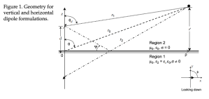 There are reasons engineers simplify things. When this paper talks about “flat earth” it is specifically speaking about an area of flat topography. This is in contrast to the normal condition of varying topography. Look at the diagram on page 2 for an example of the conditions this paper is modeling.
- Calculating electrical fields over a flat surface is much less complicated than over any sort of varying surface.
- This paper makes other assumptions that are also not true to make the calculations easier: “It is assumed that the transmitting antenna and the target (or receiver) are located above, but near the surface of a flat idealized earth (constant permittivity, ε, and conductivity, σ) ground.”
- We know with complete certainty that ground does not have constant permittivity or conductivity. They made these assumptions to make the calculations simpler and more universally applicable.
- None of the engineering simplifications in this document suggest anything about the shape of the earth.
- An Energy Budget Model to Calculate the Low Atmosphere Profiles of Effective Sound Speed at Night
- Pages: 10, 16
- https://www.arl.army.mil/arlreports/2003/ARL-MR-563.pdf
- Page 10: Nathan thinks a not-to-scale diagram somehow suggests the earth is flat? Surely you can’t be serious.
- Page 16: “To briefly examine short range acoustic attenuation at night, we use the low atmosphere profiles of wind speed, temperature, and relative humidity (shown before) as input to a flat earth, non-turbulent acoustic propagation model called the Windows (version) Scanning Fast Field Program (WSCAFFIP).”
- This very clearly states they are modeling to calculate short-range acoustic attenuation. They are using profiles to model wind, temperature, and humidity as well as topographically flat terrain. Modeling is an engineering tradeoff to reduce complexities, particularly ones that have trivially small effects on the output.
- Computationally Efficient Algorithms for Estimating the Angle of Arrival of Helicopters Using Acoustic Arrays
- https://www.arl.army.mil/arlreports/2010/ARL-TR-5118.pdf
- Page 4 refers to GPS as “global positioning system”.
- Page 17, 30, 31, 35 This document deals with a model for using acoustic signals to ascertain information about helicopters. This includes bouncing the sound off a “flat earth”. This is referring to the topography of the surface of the earth, it is not suggesting anything about the shape of the earth as a whole. It’s important to understand this document is about modeling how sound waves propagate. It’s clear Nathan simply searched this document for the word flat and did nothing more than noting the page numbers. He didn’t even read the full sentence like this for example: “The assumptions of straight-line propagation, constant reflection coefficient, or reflection off a flat earth may not be valid.” Of course, this is not referring to a flat earth model in regard to the entire world either, just the accuracy of the model within the scope this document is exploring.
- Adding Liquid Payloads Effects to the 6-DOF Trajectory of Spinning Projectiles
- Page: 7
- https://www.arl.army.mil/arlreports/2011/ARL-TR-5810.pdf
- This document models spinning projectiles with a liquid payload. This is compared to a model for spinning projectiles that are solid. These models are compared and then compared to real observations.
- The model assumes a flat earth to simplify calculations. Modeling is common in engineering to eliminate things that increase complexity without adding significant value to the output. In particular, this is about not including the topography of the land in the calculations. This is not about the earth’s shape as a whole.
- Trajectory Prediction of Spin-Stabilized Projectiles With a Steady Liquid Payload
- Page: 10
- https://www.arl.army.mil/arlreports/2011/ARL-TR-5810.pdf
- This is an updated version of document #5 from the same author. It’s still about modeling liquid-filled projectiles over flat earth or topography.
- Derivation and Definition of a Linear Aircraft Model
- Pages: 6, 35, 55, 102
- Nathan’s link: https://www.nasa.gov/centers/dryden/pdf/88104main_H-1391.pdf
- Link with searchable text: http://hdl.handle.net/2060/19890005752
- The searchable document includes blank pages from the original document so the page numbers diverge throughout the document. I will use page numbers based on Nathan’s unsearchable document.
- This document is modeling aircraft flight. There are many simplifications used to make the calculations more manageable. :
- The aircraft is assumed to be rigid. This is clearly never the case. Wings flex depending on lift. The body of the plane will twist slightly under different forces. However, these flexes have a nominal impact on the flight so can be ignored.
- The aircraft is assumed to have a constant mass. Since airplanes use fuel, this is not possible. However, the varying mass doesn’t affect the outcome enough to require inclusion so is ignored.
- The air is considered to be stationary, that is there is no wind taken into account. We all are aware there is wind, but it is left out of these calculations.
- The surface of the earth is calculated as if it is flat. Obviously, there is topography over land. This document is, in no way, suggesting hills and mountains don’t exist, they are left out of the calculations for simplicity. This is not making any reference to the earth’s shape as a whole.
- Pages 7, 8, 24 acknowledge gravity. See note on document #1.
- General Equations of Motion for a Damaged Asymmetric Aircraft
- Page: 2
- https://ntrs.nasa.gov/archive/nasa/casi.ntrs.nasa.gov/20070030307.pdf
- This document models a damaged aircraft’s flight. Being this is a model many simplifications are assumed. None of these assumed items are being claimes to be true in general:
- rigid aircraft
- flat non-rotating earth
- In contrast to several other aircraft models, this one specifically calculates the changes based on the non-symmetric weight distribution. This is an excellent example of engineering’s ability to isolate things while modeling and apply them to a larger solution. Regular airplane flight models are used in conjunction with the information in this document to provide a broader model of a damaged aircraft.
- Pages 3, 6, and 7 acknowledge gravity. See note on document #1.
- Predicted Performance of a Thrust Enhanced SR-71 Aircraft with an External Payload
- Page: 10
- https://www.nasa.gov/centers/dryden/pdf/88507main_H-2179.pdf
- “The DPS equations of motion use four assumptions that simplify the program while maintaining its fidelity for most maneuvers and applications: point-mass modeling, nonturbulent atmosphere, zero side forces, and a nonrotating Earth.”
- It seems Nathan didn’t read anything more than just the words “nonrotating Earth”. It’s very clearly stated that these assumptions are to simplify the program.
- If someone thinks this suggests anything about the shape of the earth, would it also suggest that airplanes are actually point-masses? Would it also suggest there is no turbulence in the atmosphere? No.
- This is a clear use of Idealization. This is also a clear illustration that Nathan has no idea how engineering is done.
- Derivation of a Point-Mass Aircraft Model used for Fast-Time Simulation
- On Nathan’s web page he has the title mislabeled.
- Page: 7
- https://www.mitre.org/sites/default/files/publications/pr_15-1318-derivation-of-point-mass-aircraft-model-used-for-fast-time-simulation.pdf
- This document describes a model for aircraft flight and testing avionics systems.
- Here is the quote from page 7: “Assuming a flat, non-rotating Earth, an inertial reference frame N is defined with the n1 axis aligned with east, the n2 axis aligned with north, and the n3 axis pointing up from the Earth.”
- This is an example of real-world engineering happening. Trade-offs are made in engineering to simplify things and reduce time and costs. Notice in the title of the document where it says “Point-Mass Aircraft”. This means the engineering has simplified all the mass of an airplane into a single point. Is this an admission that airplanes actually have all their mass concentrated in one point? Of course not, this is standard engineering.
- A Method for Reducing The Sensitivity of Optimal Nonlinear Systems to Parameter Uncertainty
- Page: 14
- https://ntrs.nasa.gov/archive/nasa/casi.ntrs.nasa.gov/19710018599.pdfA point-mass vehicle
- A flat, nonrotating earth
- A constant-gravity field, g = 9.8 m/sec2 (32.2 ft/sec2)
- Constant thrust and mass-loss rate
- A nonlifting body in a nonvarying atmosphere with a constant drag parameter
- Airplanes are not point masses
- Thank you for confirming gravity, see note on document #1
- Thrust and mass-loss rate is not constant
- Are airplanes non-lifting bodies? Does the atmosphere not vary? Is drag constant?
- All engineering tradeoffs that are not true, but used to simplify calculations.
- Calculation of Wind Compensation for Launching of Unguided Rockets
- Pages: 8, 10
- https://ntrs.nasa.gov/archive/nasa/casi.ntrs.nasa.gov/20040008097.pdf
- “A trajectory simulation incorporating the above requirements is presented in reference 8. In addition to the above requirements, this simulation assumes a vehicle with six degrees of freedom and aerodynamic symmetry in roll and the missile position in space is computed relative to a flat nonrotating earth. This trajectory simulation was programmed on the IEN704 electronic data processing machine and is the basis for all trajectory computations made in this paper.”
- The IBM 704 Electronic Data-Processing Machine was introduced in 1954. This is a very basic computer by today’s standards. It is severely limited in its processing ability. Aggressive tradeoffs must be taken to enable this computer to do any calculations.
- Some examples of assumptions made to simplify calculations:
- In this paper the rocket is assumed to turn instantaneously into the wind so that the vehicle axis is always tangent to the trajectory.
- These equations, however, are still limited to one plane, and also the same weighting factors in pitch and yaw are assumed.
- This paper also addresses assumptions taken from previous publications and addresses the errors introduced from these assumptions:
- It was assumed that the vehicle has roll symmetry although
the Recruit rocket motors produce an unsymmetric effect.
- It was assumed that the vehicle has roll symmetry although
- Page 3 includes the effects due to gravity. See note on document #1.
- User’s Manual for LINEAR, a FORTRAN Program to Derive Linear Aircraft Models (2768)
- Page: 16
- https://www.nasa.gov/centers/dryden/pdf/88072main_H-1259.pdf
- “Within the program, the nonlinear equations of motion include 12 states representing a rigid aircraft flying in a stationary atmosphere over a flat nonrotating earth”
- These are engineering simplifications used to make calculations easier. Other assumptions that are not true include:
- Rigid aircraft
- Stationary atmosphere – zero wind
- Page 8 includes the effects due to gravity. See note on document #1.
- User’s Manual for LINEAR, a FORTRAN Program to Derive Linear Aircraft Models (2835)
- Page: 4
- https://www.nasa.gov/centers/dryden/pdf/88112main_H-1443.pdf
- This is an updated user manual for the same program mentioned in #13.
- Determination of Angles of Attack and Sideslip from Radar Data and a Roll-Stablized Platform
- Page: 2
- https://ntrs.nasa.gov/archive/nasa/casi.ntrs.nasa.gov/19720012071.pdf
- “Equations for angles of attack and sideslip relative to both a rolling and nonrolling body axis system are derived for a flight vehicle for which radar and gyroscopic-attitude data are available. The method is limited, however, to application where a flat, nonrotating earth may be assumed. The gyro considered measures attitude relative to an inertial reference in an Euler angle sequence. In particular, a pitch, yaw, and roll sequence is used as an example in the derivation. Sample calculations based on flight data are presented to illustrate the method. Results obtained with the present gyro method are compared with another technique that uses onboard-camera data.”
- This specifically states this can only be used for applications where a flat and nonrotating earth may be assumed. There are applications where this cannot be assumed.
- Page 5 expands on this limitation:
- “This assumption limits the analysis to short-range, short-duration flights.”
- Page 8 explicitly states that the earth is rotating and instruments can measure this rotation:
- “In addition, since a roll-stabilized platform provides a true inertial reference in space, the earth’s rotation will cause readings on the gyro while the vehicle is still on the earth.”
- Also on page 17:
- “In addition to these gyro errors, there is an uncertainty of 0.25 deg/min because the earth’s rotation has not been accounted for.”
- U.S. Standard Atmosphere (1962)
- https://ntrs.nasa.gov/archive/nasa/casi.ntrs.nasa.gov/19630003300.pdf
- Page 22: “For the accuracy required in this document, it suffices to treat the surface Φ = 0 as an ellipsoid whose flattening (ellipticity) is f = 1-(b/a) = 1/298.32 where b is the semiminor axis, or polar radius.”
- In Nathan’s cherry-picking exposition he got so excited that he read this sentence without attempting to understand what it meant. The flattening of the earth or its ellipticity refers to the difference of the major and minor semi-axes of a sphere. This is due to the centrifugal force from the earth’s rotation.
- Further, this document has many mentions and tables concerning gravity. Way too many to list here. See gravity note on Document 1.
- Notably, starting on page 78 is a table labeled “ACCELERATION DUE TO GRAVITY, SPECIFIC WEIGHT, PRESSURE SCALE HEIGHT, NUMBER DENSITY, PARTICLE SPEED, COLLISION FREQUENCY, MEAN FREE PATH, AND MOLECULAR WEIGHT”
- Further, this document mentions rotation and centrifugal force due to earth’s rotation:
- Page 8: “Under the influence of gravitational and centrifugal forces this line OP will bend polewards as it rises except along the axis of rotation of the earth and along an equatorial radius extended.”
- Page 21: “The force of gravity is the resultant (vector sum) of two forces: (a) the gravitational attraction, in accordance with Newton’s universal law of gravitation, and (b) the centrifugal force, which results from the choice of an earthbound, rotating frame of reference.”
- Page 21: “The centrifugal potential Φc can be expressed as [equation omitted for brevity] where Ω the angular velocity of the earth and r cos Ψ is the distance, measured perpendicularly to the earth’s axis, from this axis to the point (r,Φ,Ψ;).”
- Page 22: “The spherical coordinates r, Φ, and Ψ are, respectively, the radial distance from the earth’s center, the longitude, and the geocentric latitude (the angle that the radius vector makes with the equatorial plane of the earth).”
- Thank you, Nathan, for including this document that admits the earth is a rotating sphere under the influence of gravity. A globe with the necessary ellipticity for a rotating sphere as Newton proved in his Principia.
- An Aircraft Model for the AIAA Controls Design Challenge
- Page: 13
- https://www.nasa.gov/centers/dryden/pdf/88248main_H-1777.pdf
- “The nonlinear equations of motion used in this model are general six-degree-of-freedom equations representing the flight dynamics of a rigid aircraft flying in a stationary atmosphere over a flat, nonrotating Earth.”
- These are engineering simplifications used to make calculations easier. Other assumptions that are not true include:
- Rigid aircraft
- Stationary atmosphere – zero wind
- Page 3 includes the effects due to gravity. See note on document #1.
- Investigation of Aircraft Landing in Variable Wind Fields
- Page: 14
- https://ntrs.nasa.gov/archive/nasa/casi.ntrs.nasa.gov/19790005472.pdf
- This is th list of assumptions made when doing the analysis:
- a) The earth is flat and non-rotating.
- b) The acceleration of gravity, g, is constant (9.8 m/sec2).
- c) Air density is constant (1.23 kg/m3).
- d) The airframe is a rigid body.
- e) The aircraft is constrained to motion in the vertical plane.
- f) The aircraft has a symmetry plane (the x-z plane).
- g) The mass of the aircraft is constant.
- h) Initial flight conditions are for steady-state flight.
- This are engineering tradeoffs:
- a) The earth is neither flat nor nonrotating, but the errors due to leaving these out of the calculations is acceptable.
- b) The acceleration of gravity is not constant, iv varies based on elevation, latitude, and variations in the earth’s composition. However, this acknowledges the effect due to gravity, see note on document #1.
- c) Air density is not constant.
- d) Airframes are not rigid.
- e) Aircraft are free to turn left or right.
- f) aircraft are not symmetrical
- g) aircraft mass varies based on fuel consumption or weapons use
- h) flights are not stead state
- A Mathematical Model of the CH-53
- Page: 25
- https://ntrs.nasa.gov/archive/nasa/casi.ntrs.nasa.gov/19810003557.pdf
- “The helicopter equations of motion are given in body axes with respect to a flat, nonrotating Earth. The helicopter is considered a rigid body with
mass symmetry about the xh – zh plane. The effects due to the engine angular momentum are neglected.” - Another list of engineering simplifications done to ease calculations:
- flat, nonrotating earth
- helicopters are rigid bodies
- mass symmetry
- engine angular momentum is neglected
- Page 4 includes the effects due to gravity. See note on document #1.
- The Development and Validation of a Piloted Simulation of a Helicopter and External Sling Load
- Pages: 6, 37, 48
- https://ntrs.nasa.gov/archive/nasa/casi.ntrs.nasa.gov/19790005912.pdf
- Page 6: “A general set of nonlinear, rigid-body equations of motion for both the helicopter and external load determines the motion of each vehicle with respect to a flat, nonrotating Earth.”
- Page: 37: “The equations of motion for both the helicopter and the external sling load are developed in body axes with respect to a flat, nonrotating Earth. It is assumed for convenience that each body is rigid and that the xh-zh plane and the xl-xl plane are planes of mass symmetry and that gyroscopic effects of engines are negligible.”
- See note on Document #19
- Page 48: “It consists of a Maltese cross with a 45-m by 45-m border. The terrain is generally flat, and provision is made for variable visibility, variable cloud-base heights, and day, dusk, and night scenes.”
- Did Nathan just search for “flat” and cite any page that had flat? This is referring to topography. Nathan, you’re lazy.
- Page 4 includes the effects due to gravity. See note on document #1.
- Atmospheric Oscillations
- Page: 13
- https://ntrs.nasa.gov/archive/nasa/casi.ntrs.nasa.gov/19650015408.pdf
- “The most one can profitably simplify the problem is to consider an isothermal atmosphere, plane level surfaces, and a nonrotating earth. This case has been handled by Eckart [1960], Lamb [1932], and Hines [l96O]. The simplification is not valid for small effects, but general, large effects m y be described and discussed.”
- More engineering simplifications. This clearly states there are problems with this simplification.
- Page: 11: “Eckart [l960]went through a second derivation in which the effect of the earth’s rotation was included.”
- Oops, Nathan, this admitted the earth rotates.
- Almost every page mentions gravity. See note on document #1.
- Stability and Control Estimation Flight Test Results for the SR-71 Aircraft With Externally Mounted Experiments
- Page: 19
- https://www.nasa.gov/centers/dryden/pdf/88733main_H-2465.pdf
- Page 10-11: “These equations assume a rigid vehicle and a flat, nonrotating Earth. The time rate of change of mass and inertia is assumed negligible. The SR-71 configurations studied herein, like most aircraft, are basically symmetric about the vertical-centerline plane.”
- These are engineering simplifications:
- rigid vehicle
- flat, nonrotating Earth
- time rate of change of mass and inertia is assumed negligible
- symmetrical about the vertical-centerline plane
- Page 2 includes the effects due to gravity. See note on document #1.
- Flight Testing a V/STOL Aircraft to Identify a Full-Envelope Aerodynamic Model
- Page: 9
- https://ntrs.nasa.gov/archive/nasa/casi.ntrs.nasa.gov/19880014378.pdf
- “For aircraft problems, the state and measurement models together represent the kinematics of a rigid body for describing motion over a flat, nonrotating Earth”
- These are engineering simplifications:
- rigid body
- flat, nonrotating Earth
- Singular Arc Time-Optimal Climb Trajectory of Aircraft in a Two-Dimensional Wind Field
- Page: 2
- https://ntrs.nasa.gov/archive/nasa/casi.ntrs.nasa.gov/20060053337.pdf
- “In our minimum time-to-climb problem, the aircraft is modeled as a point mass and the flight trajectory is strictly confined in a vertical plane on a non-rotating, flat earth. The change in mass of the aircraft is neglected and the engine thrust vector is assumed to point in the direction of the aircraft velocity vector. In addition, the aircraft is assumed to fly in an atmospheric wind field comprising of both horizontal and vertical components that are altitude-dependent. The horizontal wind component normally comprises a longitudinal and lateral component. We assume that the aircraft motion is symmetric so that the lateral wind component is not included.”
- This is simply a list of simplifying assumptions to make calculations easier.
- Point mass aircraft
- strictly vertical flight trajectory
- No change in the mass of the aircraft
- Engine thrust vector points in the direction of aircraft velocity
- Aircraft motion is symmetric
- No lateral wind
- STUDIES ON INSTABILITIES IN LONG-BASELINE TWO-WAY SATELLITE TIME AND FREQUENCY TRANSFER (TWSTFT) INCLUDING A TROPOSPHERE DELAY MODEL
- Pages: 2, 6
- https://tycho.usno.navy.mil/ptti/2007papers/paper21.pdf
- This link may be broken, use this one:
- Page 2: “The TDEV shape of the residuals (as depicted in Fig. 2, right hand) is almost flat at a level around 140 ps, and the noise type corresponds to flicker phase noise.”
- That flatness there refers to the shape of the residuals being flat at a level of 140 picoseconds. It doesn’t refer to topography or the shape of the earth.
- Page 6: “Two are rough approaches, namely a simple plane troposphere (assuming a flat Earth) and the straight “line of sight” through the spherical troposphere shell [14].”
- This notes that flat earth is a rough approach.
- This also notes that the troposphere is a sphere. Thanks, Nathan, for referencing the spherical earth.
- “In operational TWSTFT, both ground stations and the satellite spin around the rotation axis of the Earth.”
- Thank you, Nathan, for acknowledging satellites exist and that the Sagnac effect measures the rotation of the earth.
- Scale-Insensitive Detection Algorithm for FLIR Imagery
- Page: 6
- https://www.arl.army.mil/arlreports/2001/ARL-TN-175.pdf
- “For example, in some scenarios, it is assumed that the range is known to within one meter from a laser range finder or a digital map. In other scenarios, only the range to the center of the field of view and the depression angle is known, so that a flat-earth approximation provides the best estimate.”
- This clearly notes that flat-earth is an approximation.
- User Manual for the Microsoft Window Edition of the Scanning Fast-Field Program (WSCAFFIP) Version 3.0
- Page: 45
- https://www.arl.army.mil/arlreports/2003/ARL-TR-2696.pdf
- “This model works over a flat earth and non-turbulent atmosphere. Even with these restrictions, the model performs very well for many scenarios.”
- This neither claims the atmosphere is non-turbulent nor that the earth is flat. These are engineering simplifications. It also clearly states this is a restriction that performs in a limited number of scenarios.
- Path-Loss Measurements in a Forested Environment at VHF
- Pages: 8, 16, 17, 18, 19, 20, 23, 25, 26, 35
http://www.arl.army.mil/arlreports/2000/ARL-TR-2156.pdf - Page 8: “We made multipath measurements to provide confidence in the data and to get an idea of how well our measurements of the clearing represented
an ideal flat earth. We measured the path loss at a range of 410m…” - This and all the other references are referring to a topographically flat area. In no way is this referring to anything other than a topographically flat limited area.
- Pages: 8, 16, 17, 18, 19, 20, 23, 25, 26, 35
- Review of Sound Propagation in the Lower Atmosphere
- Page: 18, 208
- https://apps.dtic.mil/dtic/tr/fulltext/u2/067880.pdf
- Page 18: “In most of the topics to be discussed the problem Is to describe the sound field in a region of atmosphere above a flat earth.”
- This is referring to a topographically flat area.
- There are other assumptions and simplifications in the document that are also not true but are part of the engineering tradeoffs:
- “the source is like a point source and has spherical symmetry”
- “nonlinear effects are ignored”
- “pressure amplitudes are small in comparison to atmospheric pressure”
- Page 208 is a citation to a different publication with “flat earth” in the title. How lazy can you get to just find the words “flat earth” without even looking at the context? Nathan, grow up.
- Beacon Position and Attitude Navigation Aided by a Magnetometer
- Page: 11
- https://www.arl.army.mil/arlreports/2010/ARL-CR-650.pdf
- “This section summarizes and notates three kinds of coordinate systems. The first is the Earth-fixed coordinate system, which is fixed to the Earth with a flat Earth assumption. Denote X, Y, and Z as the unit vectors pointing in the directions of the X, Y, and Z axes, respectively. Without loss of generality, the X, Y, and Z axes point to forward, right, and down, respectively. The second is the body-fixed coordinate system, with three unit vectors Xb, Yb, and Zb pointing to the Xb, Yb, and Zb axes, respectively.”
- This is just discussing the coordinate systems. How can you not understand this?
- Jut like all the rest, there are also engineering trade offs made like assuming rigid airplane bodies.
- Automatic Target Acquisition of the DEMO III Program
- Page: 9
- http://www.arl.army.mil/arlreports/2002/ARL-TR-2683.pdf
- “In other scenarios, only the range to the center of the field-of-view and the depression angle is known so that a flat earth approximation provides the best estimate.”
- It seems Nathan missed the word “approximation” immediately after “flat earth”. Yeah, it’s an approximation that works for some circumstances.
- Modeling of Atmospheric Effects
- Page: 13
- https://www.arl.army.mil/arlreports/2000/ARL-TR-1812.pdf
- Nothing apparent on page 13, but page 28 has this: “This model works well over a flat-earth and a non- turbulent atmosphere. In the near future this model will be added to the EOSAEL.”
- More engineering assumptions:
- flat-earth
- non- turbulent atmosphere
- Neither of these are true, but can be omitted from calculations for simplification. The errors introduced by these simplifications are small and acceptable.
- Telemetry Standards
- Page: 172
- http://www.irig106.org/docs/106-17/106-17_Telemetry_Standards.pdf
- “Although the equations for the two-ray model can be rather daunting, in its simplest form, one uses flat-earth trigonometry to compute the difference in path lengths between the direct and reflected signals.”
- Doing the calculations in it’s simplest form is for a flat earth.
- This model is later stated to be inadequate:
- “Since the two-ray model is seldom adequate for predicting path loss over terrain, a wide assortment of models that include the effects of terrain has been developed. These are based on different combinations of assumptions regarding reflection, refraction, diffraction, signal blockage, Fresnel zone impingement, etc., and are available with terrain databases already included.”
- Approximate Optimal Guidance for the Advanced Launch System
- Page: 172
- https://ntrs.nasa.gov/archive/nasa/casi.ntrs.nasa.gov/19940020279.pdf
- There are not 172 pages in the cited publication.
- Page 32: “This chapter presents the modelling of motion for the rocket. Included are sections on the properties of the propulsion, aerodynamics, masses, gravity, and the atmosphere. A small expansion parameter, the ratio of the atmospheric scale height to the radius of the Earth, is then used to separate the dynamics into the primary and perturbation effects. Lastly, the equations of motion for the zeroth-order problem of flight in a vacuum over a flat Earth are presented.”
- Um, gravity? Nathan, read, don’t cherry pick.
- Do you think this is admitting that airplanes fly in a “vacuum over a flat Earth”? No, this is yet another simplification.
- Same for page 43, except there even more simplifications listed:
- vehicle is assumed to be restricted to fly in the equatorial plane
- lift, thrust, and velocity vectors all lie in the same plane
- roll angle is eliminated from the equations
- assumptions of no side force
- no sideslip
- Gravity is included in calculations in many places.
- Pages 20, 32, and 41 reference earths radius. Congratulations, Nathan, you are confirming the earth is a sphere.
- Flight Simulation Software at NASA Dryden Flight Research Center
- Pages: 4, 10
- https://www.nasa.gov/centers/dryden/pdf/88380main_H-2052.pdf
- Page 4: “The small simulation staff, large number of projects, and frequent model updates (based on flight results) have driven development of a versatile standard simulation structure. This structure, with both flat- and oblate-Earth versions, has successfully supported more than 50 different aircraft. The software is used in batch-mode, real-time pilot-in-the-loop, and flight hardware-in-the- loop operation.”
- Seriously, this mentions the oblate earth too. Are you getting lazier in your searches for the word “flat”, Nathan?
- Page 10: “In most cases, flat-Earth six-degree-of-freedom equations of motion are used. Oblate-Earth equations of motion were developed for the space shuttle simulation and later used in the NASP and follow-on simulation studies. The flat- and oblate-Earth equations of motion use a hybrid axis system that allows forces and moments to be added in the axis systems for which they are commonly computed, thus reducing axis transformations.”
- Oops, this also references oblate earth equations were used for Space Shuttle modeling. Nathan, you just confirmed the Space Shuttle was modeled using oblate earth equations.
- Simulator Aero Model Implementation
- Page: 10
- https://www.aviationsystemsdivision.arc.nasa.gov/publications/hitl/rtsim/Toms.pdf
- “The above three equations, plus the three translational equations comprise the equations of motion for the rigid body aircraft.”
- “For the flat, non- rotating earth considered here, any fixed frame of reference can be employed as an inertial frame.”
- More engineering simplifications:
- rigid body aircraft
- flat, non- rotating earth
- Page 19 includes the effects due to gravity. See note on document #1.
- Design and Implementation of Flight Visual Simulation System
- Page: 3
- https://arxiv.org/pdf/1212.0365.pdf
- “In this paper, the FVSS is based on two assumptions:
a. Flight area is the space above ground level where the rotation of earth and the curvy motion of mass center of earth are neglected.
b. Aircraft is an ideal rigid body and influence from aircraft body elastic deformation and rotating parts are not considered.” - Engineering tradeoffs:
- rotation of the earth is neglected
- This is a clear admission that the earth rotates.
- Aircraft is an ideal rigid body
- influence from aircraft body elastic deformation and rotating parts are not considered
- rotation of the earth is neglected
- Page 3 includes the effects due to gravity. See note on document #1.
- A Discussion of Methods of Real-Time Airplane Flight Simulation
- Page: 11
- http://citeseerx.ist.psu.edu/viewdoc/download?doi=10.1.1.510.7499&rep=rep1&type=pdf
- “Flat-Earth Coordinates. In many flight simulators, global navigation is not important. For example, the range of flight could be limited to a small area, or the simulator might not care about the airplane’s location. In such cases, it is appropriate to model the Earth as a plane half-space rather than an oblate spheroid. Then, the simulator need not worry about how the local horizontal plane changes as the airplane flies around the Earth. This simplifies the bookkeeping in the simulator considerably.”
- This sections explains the tradeoffs well.
- Pages 6, 13, and 21 includes the effects due to gravity. See note on document #1.
- Page 10 references earth’s radius. Yay, the earth is a sphere. Of course, this is not news.
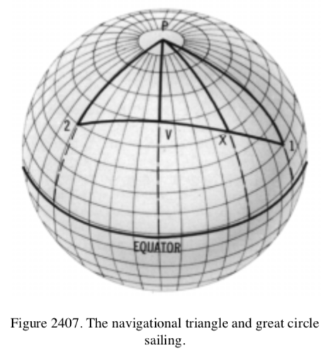
- The American Practical Navigator: An Epitome of Navigation
- Pages: 351, 355, 573, 636
- https://msi.nga.mil/Publications/APN
- This link sometimes has issues downloading, I had to different times on different days. Here is a direct download of the PDF I was finally able to download:
- Page 351: “For example, when the navigator uses his latitude graduations as a mile scale to compute a great-circle course and distance, he neglects the flattening of the earth at the poles.”
- Nathan, you can’t just search for “flat” without reading the context. You just admitted the earth is an oblate spheroid.
- Page 355: “Plane sailing solves problems involving a single course and distance, difference of latitude, and departure, in which the earth is regarded as a plane surface. This method, therefore, provides solution for latitude of the point of arrival, but not for longitude. To calculate the longitude, the spherical sailings are necessary. Do not use this method for distances of more than a few hundred miles.”
- Again, Nathan, this admits that plane sailing on only accurate for short distances. Thus, evidence for a spherical earth.
- Page 573: “backshore, n. That part of a beach which is usually dry, being reached only by the highest tides, and by extension, a narrow strip of relatively flat coast bordering the sea. See also FORESHORE.”
- This is in the glossary defining the word “backshore”. Note that is says “relatively flat”. This is just a small section of flat topography. Again, just searching for the word flat without context doesn’t help you. Stop being lazy.
- Page 636: This is a section of the glossary, but nothing referencing flat is on this page. However, page 633 has this which he may be intending: “Krassowski ellipsoid of 1938. A reference ellipsoid of which the semi-major axis is 6,378,245 meters and the flattening of ellipticity equals 1/298.3.”
- This is yet another reference to the ellipsoid shape of the earth.
 Page 360 has an excellent reference to the earth as a globe. See the embedded image on the right.
- Page 11: “The earth is an oblate spheroid (a sphere flattened at the poles). Measurements of its dimensions and the amount of its flattening are subjects of geodesy. However, for most navigational purposes, assuming a spherical earth introduces insignificant error. The earth’s axis of rotation is the line connecting the North Pole and the South Pole.”

- Page 620: “gyrocompass, n. A compass having one or more gyroscopes as the directive element, and which is north-seeking. Its operation depends upon four natural phenomena, namely gyroscopic inertia, gyroscopic precession, the earth’s rotation, and gravity. When such a compass controls remote indicators, called GYRO REPEATERS, it is called a master gyrocompass. See also DIRECTIONAL GYRO MODE.”
- Page 23: “The geoid is that surface to which the oceans would conform over the entire earth if free to adjust to the combined effect of the earth’s mass attraction and the centrifugal force of the earth’s rotation. The ideal ocean surface would be free of ocean currents and salinity changes. Uneven distribution of the earth’s mass makes the geoidal surface irregular.”
- Page 9: “Satellite navigation uses artificial earth satellites for determination of position.”
- Page 644: “magnetic pole. 1. Either of the two places on the surface of the earth
where the magnetic dip is 90°, that in the Northern Hemisphere be- ing designated north magnetic pole, and that in the Southern Hemisphere being designated south magnetic pole. Also called MAGNETIC DIP POLE. See also MAGNETIC LATITUDE, GEOMAGNETIC POLE, MAGNETIC LATITUDE. 2. Either of those two points of a magnet where the magnetic force is greatest.” - This book is full of references to gravity, the earth’s rotation, and the sphericity of the earth. Nathan, you should read it, you could learn a lot.
- The Production of Firing Tables for Cannon Artillery
- Pages: 10, 22, 34, 110
- https://apps.dtic.mil/dtic/tr/fulltext/u2/826735.pdf
- Direct PDF Download: 40 826735
- Page 10 does not reference flat or stationary, but does mention “Accelerations due to the rotation of the earth” and “Acceleration due to gravity”.
- Page 22 same as page 10.
- Page 34: “Compensation for Rotation of Earth. The final computations to be made in preparation for determining the ballistic coefficient are those to determine the coefficients used in the equations of motion to compensate for the rotation of the earth.”
- Nathan, are you sure you want to cite this source?
- Page 110 is just a trajectory chart with a range up to 2km. It is unclear what Nathan means by referencing this page.
- The following are Nathan’s specific notes on this source:
- #40 on pages 66 – 68 of 115 references “Rotation of Earth”:
1) Doc #40 does NOT account for curvature of earth
2) Doc #40 represents the “Rotation of Earth” in an equation for “particle theory”, whereby, when the numerical value of zero (0) is plugged in for the variable to account for the alleged rotation it does not negatively impact the rest of the equation and it is able to compute. - MCToon response: When firing over land the curvature of the earth is immaterial, the topography is what matters. Plugging in a zero for the rotation of the earth will not cause an error in the equation, however, it will cause the projectile to miss its target.
- #40 on pages 66 – 68 of 115 references “Rotation of Earth”:
- See notes on item #44, for the same rotation admissions.
- Field Artillery Manual Cannon Gunnery
- Page: 175, 192
- https://armypubs.army.mil/epubs/DR_pubs/DR_a/pdf/web/tc3_09x81.pdf
- Direct PDF Download: 41 tc3_09x81
- #41, “Field Artillery Manual Cannon Gunnery”, page 48 of 664: “3-55. If a round were fired in a vacuum, gravity would cause the projectile to return to the surface of the earth. The path or trajectory of the projectile would be simple to trace. All projectiles, regardless of size, shape, or weight, would follow paths of the same parabolic shape and would achieve the same range for a given muzzle velocity and quadrant elevation.”Nathan Roberts’s reply: The “parabolic shape” of the trajectory of the bullet is caused by density, not gravity or the alleged curvature of a spherically shaped earth.
————————–
Doc #41, “Field Artillery Manual Cannon Gunnery”, page 48 of 664:
3-57. Gravity causes a projectile in flight to fall to the earth. Because of gravity, the height of the projectile at any instant is less than it would be if no such force were acting on it. In a vacuum, the vertical velocity would decrease from the initial velocity to zero on the ascending branch of the trajectory and increase from zero to the initial velocity on the descending branch, Zero vertical velocity would occur at the summit of
the trajectory. For every vertical velocity value on the upward leg of the ascending branch there is an equal vertical velocity value downward on the descending branch. Since there would be no resistance to the forward motion of the projectile in a vacuum, the horizontal velocity component would be a constant. The acceleration caused by the force of gravity (9.81 m/s) affects only the vertical velocity.”Nathan Roberts’s reply: Gravity is an unproven theory, buoyancy is proven. Bullets fall because they are heavier than the medium they are within, that being the air.
————————–
Doc #41, “Field Artillery Manual Cannon Gunnery”, page 49 of 664:
“The standard (chart) range is the range opposite a given elevation in the firing tables. It is assumed to have been measured along the surface of a sphere concentric with the earth and passing through the muzzle of a weapon. For all practical purposes, standard range is the horizontal distance from the origin of the trajectory to the level point.”Nathan Roberts’s reply: IF “It is assumed to have been measured along the surface of a sphere concentric with the earth”, then why in the very next sentence does it state “For all practical purposes, standard range is the horizontal distance from the origin of the trajectory to the level point.”
————————–
Doc #41, “Field Artillery Manual Cannon Gunnery”, page 51 of 664:
“Deflection effects. Some of the deviations from the standard conditions affecting deflection
are:
* Drift.
* Crosswind.
* Rotation of the earth.”Nathan Roberts’s reply: On page 192, “Rotation of the earth” is established as an “unproven theory”, which holds zero bearing in reality.
————————–
Doc #41, “Field Artillery Manual Cannon Gunnery”, page 132 of 664:
5-36. The third condition is valid met corrections considered by each of the firing platoons. This includes the met message valid for the firing platoon, propellant temperature, projectile weight, vertical interval, and corrections for earth rotation.Nathan Roberts’s reply: On page 192, “Rotation of the earth” is established as an “unproven theory”, which holds zero bearing in reality.
————————–
Doc #41, “Field Artillery Manual Cannon Gunnery”, page 186 of 664:
“Range (Column 1). This is the distance measured from the muzzle to the target on the surface of a sphere concentric with the earth. When chart range is used as the entry argument for this table, it is expressed to the nearest 10 meters and interpolation is necessary.”Nathan Roberts’s reply: The same response given to “sphere concentric with earth” mentioned on page 49 applies here too. - MCToon response:
- Earth’s rotation is a scientific fact. It has been measured in many ways: See here for several measurements of earth’s rotation.
- Gravity is not an “unproven theory”. Gravity is a law of nature. It is properly called the Law of Gravitational Attraction. See here for several direct measurements of gravity.
- The radius of the earth is not unproven, it is a scientific fact. See here for rigorous and detailed measurements of the earth’s radius.
- Field Artillery Gunnery
- http://militarynewbie.com/wp-content/uploads/2013/10/FM-3-09.8-FIELD-ARTILLERY-GUNNERY.pdf
- Direct PDF Download: 42 FM-3-09.8-FIELD-ARTILLERY-GUNNERY
- It is unclear why Nathan included this document as he did not include a reference to any page and searching does not indicate anything about flat or stationary earth.
- Page 39 does acknowledge the earth is a sphere: “The distance measured on the surface of a sphere concentric with the earth from the muzzle to a target at the level point.”
- Thanks, Nathan.
- TTP for the Field Artillery Cannon Gunnery
- https://www.globalsecurity.org/military/library/policy/usmc/mcwp/3-16-3/mcwp3-16-3.pdf
- Direct PDF Download: 43 mcwp3-16-3
- Similar to #42. it is unclear what Nathan is referencing to in this document.
- Page 94 does admit that there are satellites in orbit around the earth for the Global Positioning System: “The satellite constellation. Ensures worldwide coverage with a minimum of four satellites within electronic line of sight to any point on the earth.”
- Thanks, Nathan.
- See notes on item #44, for the same rotation admissions.
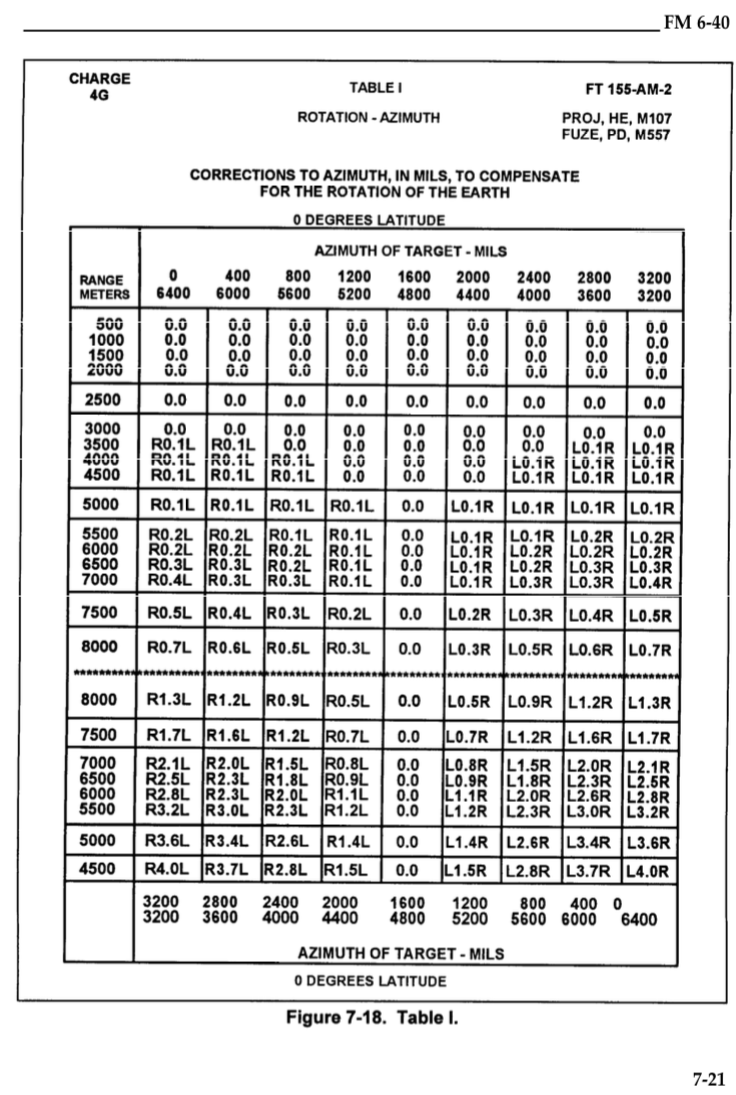
- Tactics, Techniques, and Procedures for the field artillery Manual Cannon Gunnery
- https://www.marines.mil/Portals/1/Publications/mcwp3_16_4.pdf
- Direct PDF Download: 44 mcwp3_16_4
- Nathan doesn’t specifically state what page he is referring to. It seems apparent he is referring to pages 4 and 129 where it says “NO ROTATION OF THE EARTH”.
- This is included in a list of “standard conditions” used to determine the firing solution for artillery:
- Air Temperatur: 59°F
- Air Density 100 percent (1,225 gm/m^2)
- No wind
- Gun, target, and MDP at same altitude
- MDP is “meteorological datum plane”
- Accurate range
- No rotation of the earth
- Standard weapon, projectile, and fuze
- Propellent temperature (70°F)
- Firing table muzzle velocity
- No drift.
- It is clear to anyone that these conditions are never true. These are simply the starting point for calculating the firing solution. The pages following this chart include how to include corrections for each of the items listed on this list.
- Page 208 gives instructions to include adjustments for the rotation of the earth:
 “Table H is used in the solution of concurrent and subsequent met. The extracted value is the correction to range in meters for the rotation of the earth at 0° latitude. A correction for any other latitude is extracted from the small table at the bottom of Table H and is multiplied by the correction from the table. The asterisks extending across the table denote the changeover point from low-angle to high-angle fire.”
 “Table I is used in the solution of concurrent and subsequent met. There are tables for every 10° latitude starting from 0° north or south latitude to 70° north or south latitude. The extracted value is the correction to deflection in mils, for the rotation of the earth. The asterisks extending across the table denote the changeover point from low-angle to high-angle free.”
- The list of standard conditions is the starting point of items that exist and must be added in to correctly produce a firing solution. This is a clear indication that rotation exists.

Flight has been modeled over a spherical earth: https://www.math.hmc.edu/~dyong/math164/2008/zitter/finalreport.pdf
